

Appearance
Why pixel grids matter
A single logical pixel may cover several display pixels, span a fractional distance, or be stretched differently along the two axes. A CRT treatment needs an appropriate scale for its scanline structure; an LCD treatment needs a scale and alignment for its cells. Applying either solely at the output pixel scale can produce a much finer pattern than the artwork suggests.
Beamline’s Pixel Grid control sets that treatment scale.
Three different resolutions
A game's resolution can refer to three different things:
| Domain | What it describes | What it does not establish by itself |
|---|---|---|
| Source framebuffer or resource | The dimensions of an actual GPU image used in rendering | That it contains the whole scene, or that its storage dimensions match the artwork's logical grid |
| Logical composition grid | The coordinate system in which artwork, camera placement or scene composition is organized | That a texture with those dimensions ever exists |
| Presented lattice | The repeating pixel-scale structure visible in the final image, including its spacing and alignment | The identity, dimensions or sampling rules of an upstream resource |
A game can draw low-resolution artwork directly into a large framebuffer. Conversely, a small texture can be a bloom pass or minimap rather than the composition surface. Padding, filtering, cropping, UI and later passes can separate all three domains.
For a presented lattice, pitch is the distance between cells in presentation pixels. Phase is their offset: where those cells begin. In one axis, a useful coordinate model is:
text
logical coordinate = (presentation coordinate - phase) / pitchA 5:3 picture on a 16:9 screen


Suppose a game composes a 400×240 image and stretches it to fill 1920×1080. The resulting pitches would be:
text
X: 1920 / 400 = 4.8 presentation pixels per cell
Y: 1080 / 240 = 4.5 presentation pixels per cell
A single square-cell pitch gives the wrong dimensions. Using 4.8 on both axes suggests 400×225; using 4.5 suggests roughly 427×240. We need independent X/Y measurements to describe the original 400×240 stretch.
Real images can combine several mappings or lose recognizable spacing through filtering.
Gravity Circuit offers a concrete example. These captures show the same tutorial scene at 1920×1080 with Beamline's treatment off. Force Ratio uses an integer scale with bars around the picture. Best Fit fills the height while preserving its proportions. Stretch to Fit fills the screen by widening the picture.
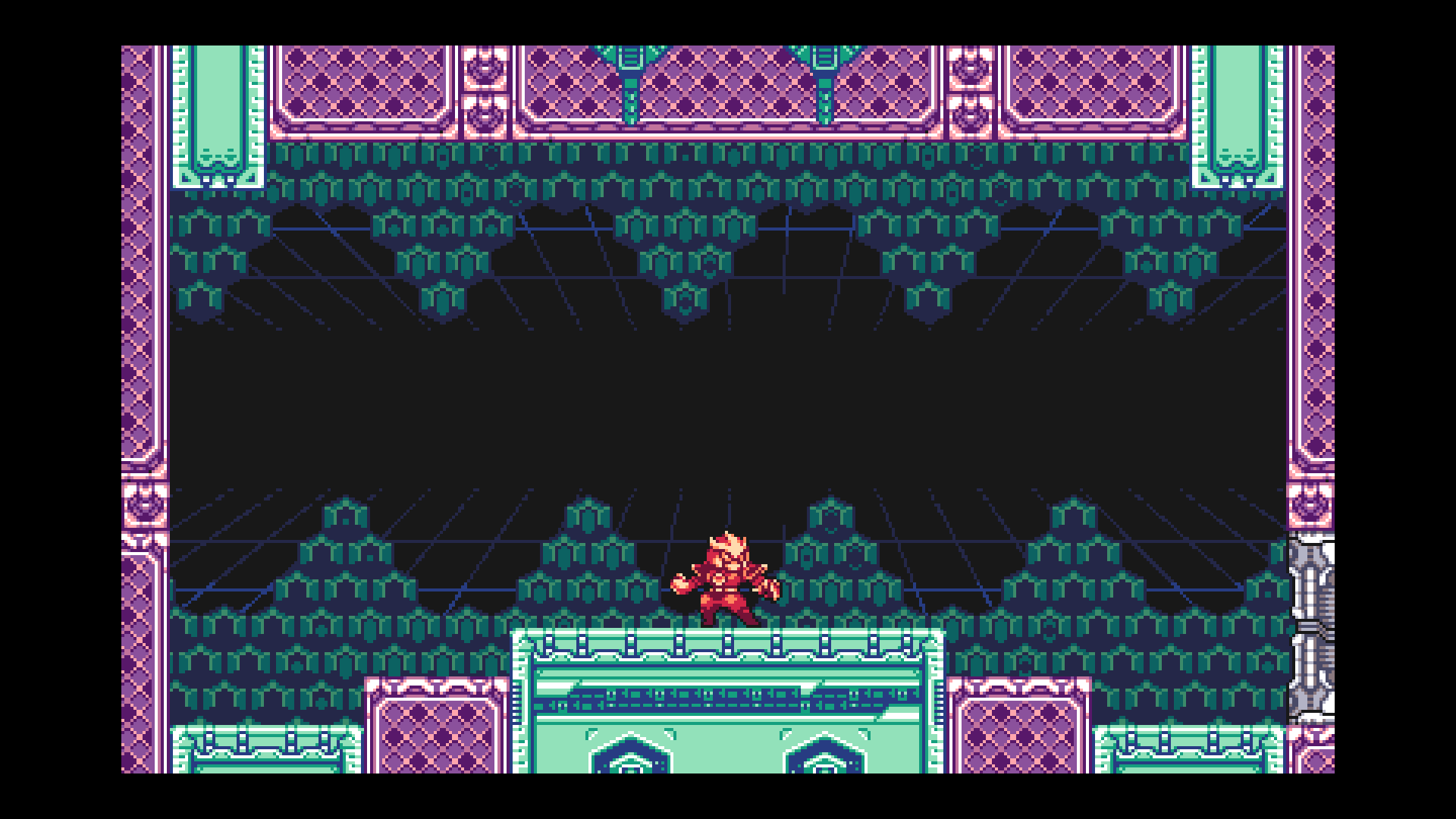
1600×960 content; 4× on both axes
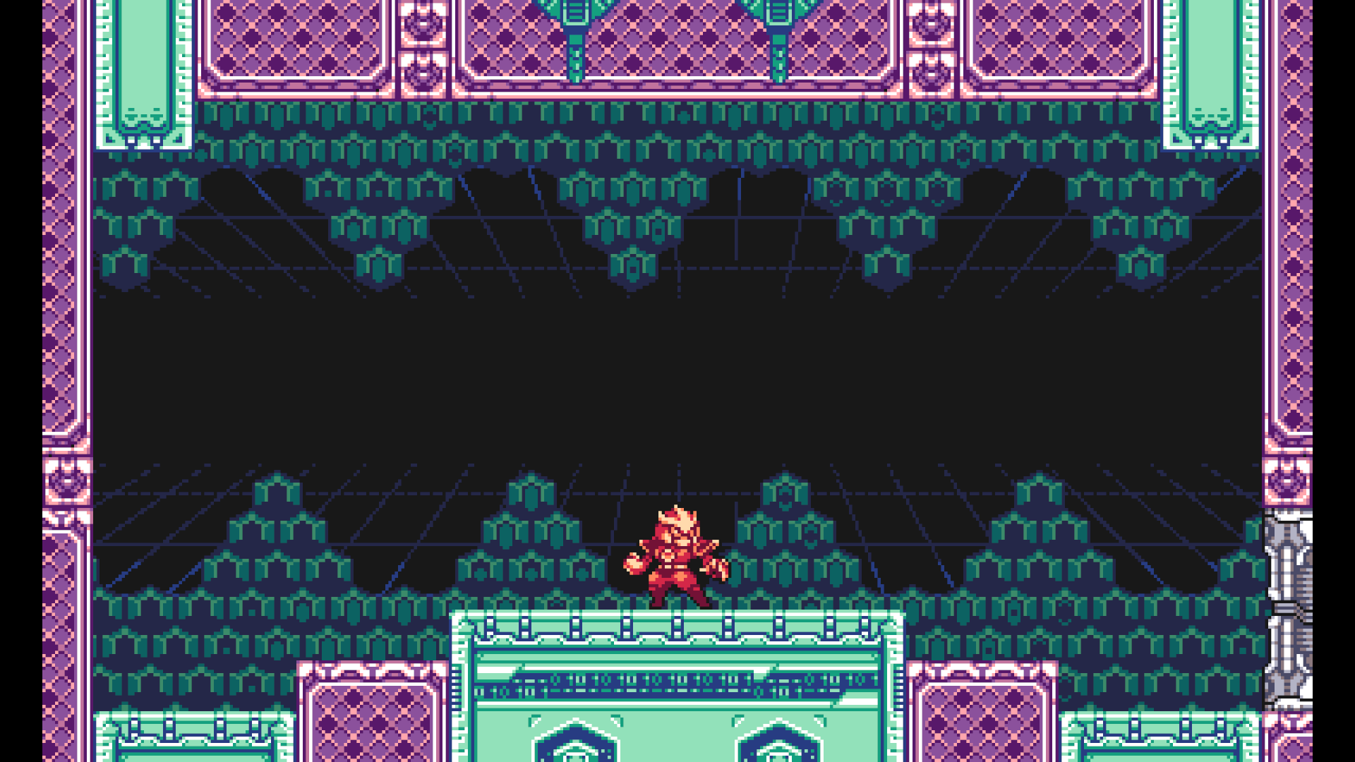
1800×1080 content; 4.5× on both axes
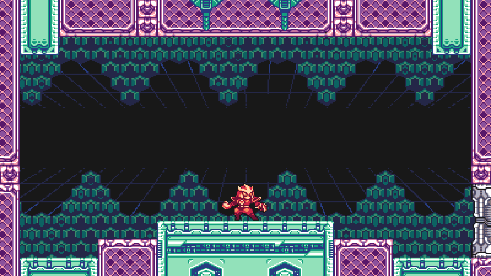
1920×1080 content; 4.8× across, 4.5× down
Grid modes
The overlay guide explains Screen, Auto, Manual and Virtual. Auto uses a saved measurement of the displayed grid; Manual chooses treatment dimensions, while Virtual also resamples the image.